|
|
|
|
|
The solution to the problem of heat losses to a gas filling came in 1912 at the Schenectady Research Laboratories of the General Electric Company. Dr. Irving Langmuir discovered that although the gas is flowing very rapidly inside the lamp, there is always a film of stationary gas a few millimetres thick around the filament - now known as the Langmuir Sheath. By learning to work with this sheath he made the modern high efficiency gas-filled lamp a commercial reality. GE put the first nitrogen-filled lamps on the market in 1913. They were 110V lamps of 750W and 1000W in spherical bulbs.
By substituting the long straight wire for a tightly coiled filament, it was found that if the spacing between adjacent windings is less than the thickness of the Langmuir sheath, then the stationary gas layer around one coil joins with the next, preventing gas flow between individual coils. As a result the surface area of the filament exposed to the moving gas is reduced, so gas losses also fall and the filament runs hotter. The relative surface area of wire exposed to the cooling effects of the gas is shown in Figure I10, which represents the end views of a straight wire, a single coil, and a coiled-coil filament surrounded by the flowing gas which rises around the filaments due to thermal convection effects within the bulb. Note how the gas flow does not contact the filament or move between the coils, but rather flows around the entire body avoiding the sheath of stationary gas - and that the thickness of this sheath is approximately the same irrespective of the filament dimensions.
|

Figure I10 - Gas Flow around Hot Lamp Filaments - End View
|
Although coiled filaments do still lose some heat to the gas by conduction and convection, for the vast majority of lamps the heat loss is reduced so tremendously that the benefits of reduced filament evaporation and hotter operation outweigh the remaining energy loss. However it is important not to forget the importance of filament geometry and its desired operating temperature when designing a gas-filled lamp.
|
A typical single coil gas-filled lamp is illustrated in Figure I11. The coil is mounted in horizontal ring, known as the C-9 Wreath configuration, so that the cooling effect of the gas is the same over its entire length when the lamp is operated in the most common vertical position. If it was mounted axially as with the earlier vacuum lamps, then given the long length of a typical single coil filament, the upper end would run hotter because hot gas rises upwards, and the temperature gradient would cause the top of the filament burn out prematurely. See Figure I9 on the previous page for a visualisation of this effect. This is partly why ordinary single coil incandescent lamps deliver the longest life and best performance when they are operated vertically cap-up or cap-down, because then no part of the filament is overheated by convection currents.
The introduction of coiled filaments simplified production - owing to its reduced length a number of support wires could be eliminated, and the bulb volume was reduced. Thus it brought not only a performance improvement, but also a cost reduction. |
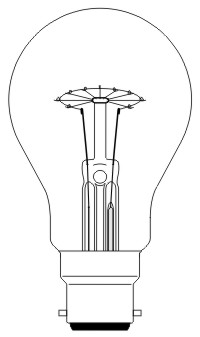 Fig.I11-Coiled Filament
 |
| Another result of coiling is to produce a black body effect due to multiple reflections of the radiation within the coil. This increases the brightness of the interior of the coil to about 175% of the exterior brightness. The massing of the filament into a smaller space is also advantageous, as for practical purposes it can be considered more of a point source allowing the fittings designers to predict performance with more accuracy. |
Coiled-Coil Filaments
| Since the 1917 patent of Bernie Lee Benbow of General Electric USA, it was realised that a coiled-coil filament would yield still further gains in efficacy, by presenting an even smaller surface area available for cooling. However there were numerous technical difficulties involved in manufacturing such lamps, and it took many more years before such lamps were commercialised - by which time that patent had virtually expired. Until then only a few special projection lamps were made, which capitalised on the reduced dimensions of the coiled-coil filament for improved optical performance, and where the short lifetime of these early filaments was acceptable. |
The first experimental general service lamp to employ a coiled-coil filament is illustrated in Figure I12. This was developed in 1924 at the Hirst Research Laboratory of the Osram-GEC Wembley Works in London. It is believed to be a high voltage GLS lamp of approximately 100W rating. But there were still many technical difficulties which delayed the market launch for almost another decade, until 1933 in Britain and Europe, and 1936 in America. |
 Fig.I12 - Experimental Coiled-Coil of 1924
 |
The principal reason for the delay was due to the development time necessary to build fully mechanised production equipment to mount the delicate coiled-coils without human intervention. Even a century ago, lamps were required in such vast quantities and made to such tight dimensional tolerances that manual assembly was out of the question – indeed it is for this reason that the incandescent lamp holds the title of being the first article of any kind to be mass produced with every operation being executed by fully mechanised equipment. Additionally it was found that a perfect coiled-coil will give highly variable performance if mounted by inferior means. Any process variation that mounts the coil with differing amounts of tension will change the coil temperature, with disastrous consequences on life and efficacy. Breakdown of the gas-filling across the shorter filament was also troublesome, and for the first time, fast-acting fuses had to be developed for incorporation within the lamp because ordinary house-wiring fuses could not be relied upon to cut out quickly enough in case a high current arc formed across the filament.
Once perfected, it was found that the increase in efficacy after the second coiling is considerable, but not so significant as the improvement from the primary coiling. However the coiled-coil offers additional advantages. Because it is shorter it requires fewer support wires - sometimes none at all being necessary. This brought a small saving in materials, and allowed machine speeds to be increased with a consequent reduction in lamp cost. Each support wire also causes local cooling and reduces light output by approximately 1%, so the lamp is more efficient with fewer supports. |
 Fig.I13 - Demonstration of Coiling Effect
 |
The effects of coiling and heat losses to the gas filling are visualised in the demonstration lamp of Figure I13, made by the author at the works of GE Lighting, Leicester. The filament is an ordinary 240V 60W coiled-coil type, but part of it has been stretched out to a single coil, and the remaining portion completely unwound to a straight wire. The entire filament is made from the same piece of tungsten wire, all the same diameter. The bulb is filled with the standard 85:15 Argon:Nitrogen mixture. When switched on at quite a low voltage, the coiled-coil lights up brightly. As current is increased the single coil begins to glow, but even at 240V the straight wire produces no light at all. |
Coiled-coiling has the greatest effect on the small diameter filaments as these have the highest surface area to volume ratio, and the most to gain. For a 230V 40W lamp the increase in efficacy is about 20% over the single-coil. It is about 10% for 100W, but only a few percent with 150W. Similarly for American 110-130V filaments the lower voltage calls for higher current and thicker filaments, and the benefit is not so significant.
With this in mind it might be wondered why coiled-coil lamps were not produced below 40W rating for the high voltages, and 60W rating for the medium voltages, until as late as the 1970s. This has to do with the differences in heat losses for vacuum vs gas-filled lamps, as described on the next page. The 230V 25W filament, for instance, is so fine that even after coiled-coiling its surface area to volume ratio remains rather high, and the heat loss to the gas filling would outweigh the benefit of reduced evaporation. Consequently it is better to make such lamps with vacuum atmosphere - and in this case, filament coiling and coiled-coiling brings no benefit as there are no gas losses.
Nevertheless, coiled-coil low wattage lamps were eventually introduced. This was done purely for reasons of cost reduction, because the coiled-coil filaments are shorter and require fewer filament supports, and such lamps can be assembled on higher speed machines at lower cost. Incidentally some manufacturers encountered a problem in this area. The highest speed GLS machines are only capable of making gas-filled lamps, because vacuum lamps take too long to pump. To gas-fill a 230V 25W coiled-coil lamp reduces its efficacy and light output vs the vacuum single coil types. To counteract this the lamp power was increased to 25.75W - but the wattage stamped on the lamps remains 25W instead of correctly rounding up to 26W.
Coiled-coils are also found in many higher power lamps even though this geometry brings little benefit in reduced gas losses. Once again this is due to the simple construction with fewer supports, and the possibility to reduce bulb sizes. Many high wattage projector lamps also use coiled-coil filaments, because their compact shapes work better in the optical system.
It should be noted that the temperature of a coiled coil filament is no greater than for the single coil type, so life is the same. All other things being equal the temperature after the second coiling would rise, with a consequent life reduction. To avoid this the wire is made slightly longer, leading to a reduction in power input for an equivalent temperature. In order to maintain the standard range of lamp wattages the power is brought back to normal by increasing wire diameter. The wire for coiled-coil filaments is therefore slightly longer and thicker than for single coils. Due to the greater mass of incandescent metal it radiates more light. |
Triple-Coil Filaments
In recent years there has been some activity to develop a triple coil filament, and such a product has been commercialised in Japan by Toshiba. This offers no significant increase in luminous efficacy, but coil dimensions are reduced such that it approaches a point-source, and outstanding optical control can be attained in small reflectors. Controlling the degree of filament sag by modification of the tungsten metallurgy was a key challenge that had to be overcome, while in parallel limiting the concentration of potassium dopant in the tungsten wire to avoid problems of arcing due to the unusually high voltage gradient between adjacent coils. |
 Fig.I14 - Triple Coil v Coiled-Coil Filament
 |
|
|
|
|
|


